
FLAT PANEL FOUNDATIONS TV STAND-PFFPS - TV Stand SANUS - Free user manual and instructions
Find the device manual for free FLAT PANEL FOUNDATIONS TV STAND-PFFPS SANUS in PDF.


| Product Type | TV floor stand with shelves |
| Brand | SANUS |
| Model | FLAT PANEL FOUNDATIONS TV STAND-PFFPS |
| TV Compatibility | Flat screen 30 to 50 inches, weight up to 59 kg |
| Materials | Steel, glass, plastic |
| Number of shelves | 2 glass shelves |
| Adjustable height | Adjustable column with multiple positions |
| TV mounting | Monitor brackets with security bolts |
| Mounting type | Floor stand (base on floor) |
| Compatible VESA standards | VESA 100x100 to 400x400 (via included bolts) |
| Maintenance | Clean with a soft, dry cloth, avoid abrasive products |
| Safety | Security bolts to lock the TV onto the stand |
| Spare parts | Available upon request from SANUS customer service |
| Warranty | Check with retailer or SANUS for terms |
| Customer service | 1-800-359-5520 (USA), +31 (0)20 5708938 (Europe) |
| Country of origin | Manufactured by Sanus Systems, USA |
Frequently Asked Questions - FLAT PANEL FOUNDATIONS TV STAND-PFFPS SANUS
User questions about FLAT PANEL FOUNDATIONS TV STAND-PFFPS SANUS
0 question about this device. Answer the ones you know or ask your own.
Ask a new question about this device
Download the instructions for your TV Stand in PDF format for free! Find your manual FLAT PANEL FOUNDATIONS TV STAND-PFFPS - SANUS and take your electronic device back in hand. On this page are published all the documents necessary for the use of your device. FLAT PANEL FOUNDATIONS TV STAND-PFFPS by SANUS.
USER MANUAL FLAT PANEL FOUNDATIONS TV STAND-PFFPS SANUS
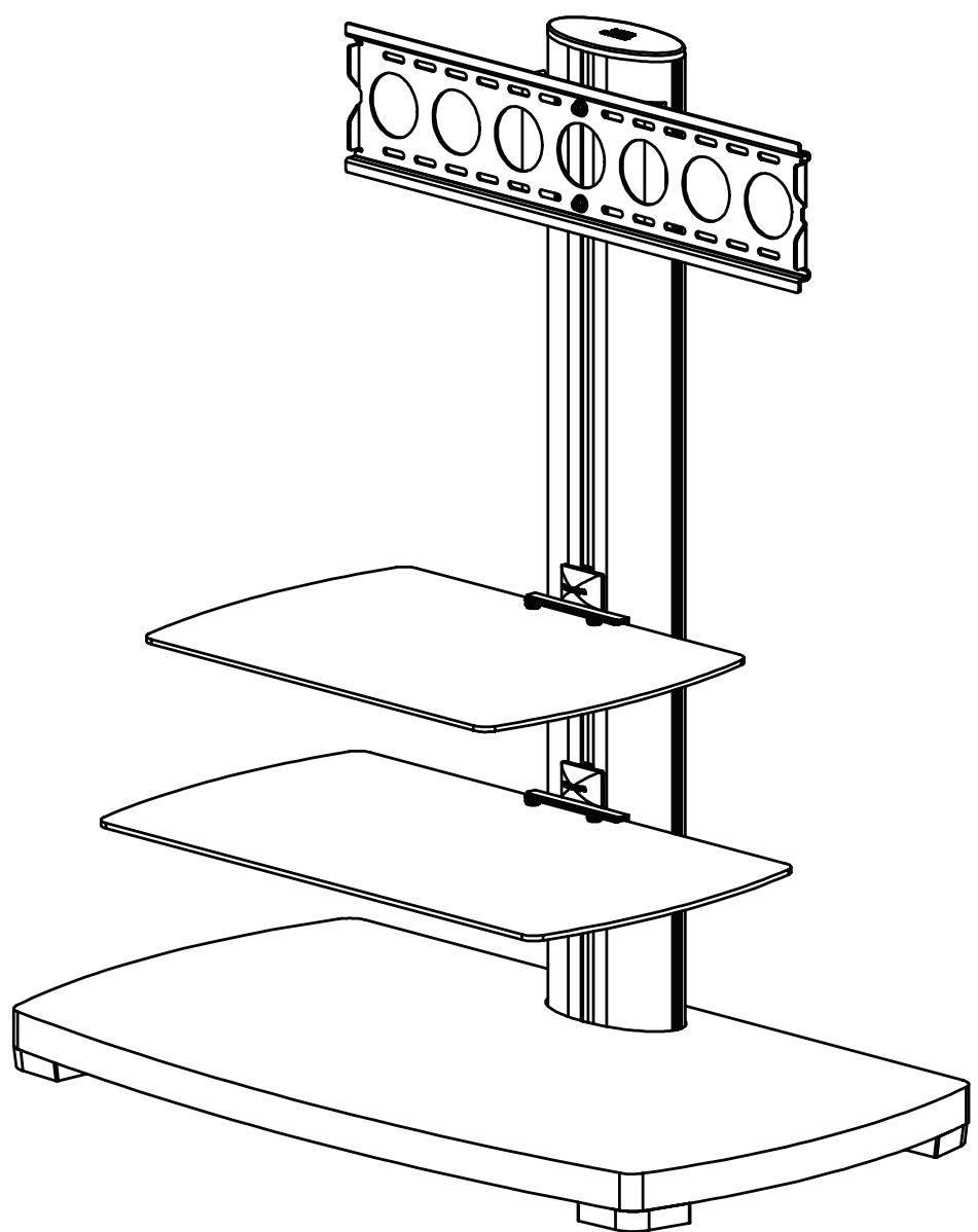
International Assembly Instructions for model PFFP2

SANUS SYSTEMS
THE UNION OF FORM AND FUNCTION
Assembly Instructions for Sanus Systems Platinum Furniture Model: PFFP2
Thank you for choosing Sanus Systems Platinum Furniture. The PFP2 is designed to support a 30” to 50” flat panel television up to 130 lbs. If you have any questions regarding this or any other Sanus Systems product, please contact us at 800.359.5520 or visit us at www.sanus.com. Our customer service representatives can assist you quickly with any issues regarding assembly or missing parts. Check carefully to make sure none of the parts are missing or defective. Never use defective parts. Replacement parts for products purchased from an authorized dealer will be shipped directly to you. Please call Sanus Systems before returning products to the retail store where you purchased them.
Required Tools: Wrench or Socket Set, Phillips Screw Driver
Parts: Some parts not shown at same scale*
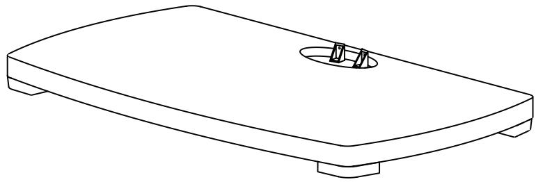
(1) Base - a
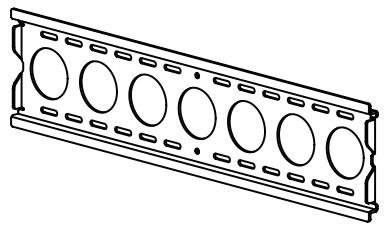
(1) Wall Bracket - b

(1) Pillar - g
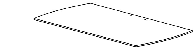
(1) Large Glass Shelf - c

(1) Right Monitor Bracket - e
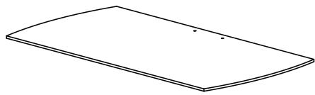

(1) Small Glass Shelf - d
(1) Left Monitor Bracket - f
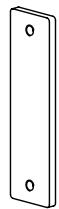
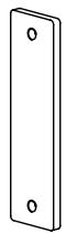
(1) Wall Plate - h*
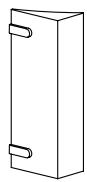
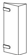
(2) Wall Bracket Spacer - i*
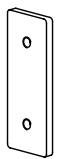
(2) Shelf Plate - j*
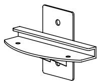
(2) Shelf Bracket - k*
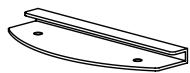
(2) Glass Shelf Washer - 1*
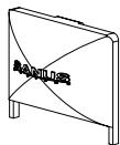
(2) Shelf Bracket Cap - m*
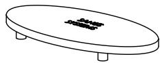
(1) Top Cap - n*
Hardware: All hardware shown as actual size
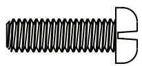
(2) M6 x 20 Bolt - o
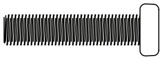
(2) M8 x 35 Bolt - p
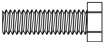
(2) M12 x 40 Bolt - q
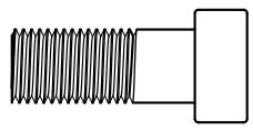
(6) M8 Allen Bolt - r
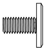
(4) 1/4-20 Allen Bolt - s
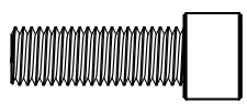
(2) Safety Bolt - t

(8) M8 Washer - u
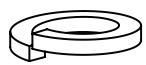
(6) Spring Washer - v

(4) Plastic Washer - w

(2) M12 Washer - x
TV Mounting Hardware:
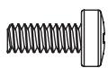
(4) M4 x 12 Bolt - y
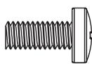
(4) M5 x 12 Bolt - z
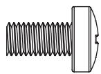
(4) M6 x 12 Bolt - aa
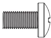
(4) M8 x 16 Bolt - bb
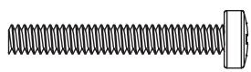
(4) M4 x 30 Bolt - cc
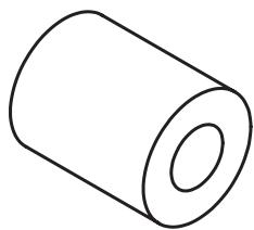
(4) M6/M8 Spacer - nn
Step 1: Secure Pillar to Base
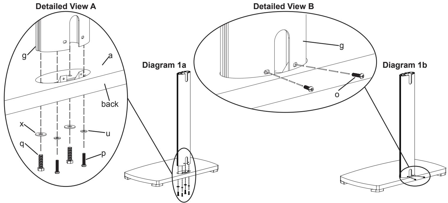
Attach the Pillar (g) to the Base (a) by placing each M12 x 40 Bolt (q) through an M12 Washer (x), each M8 x 35 Bolt (p) through an M8 Washer (u). Then thread each Bolt up through the Base and into the Pillar as shown in Diagram 1a. The M12 x 40 Bolts should be threaded into the front two holes of the Pillar, while the M8 x 35 Bolts should be threaded into the back two holes of the Pillar. Tighten the M12 x 40 Bolts with a wrench, and tighten the M8 x 35 Bolts with a Phillips screw driver. Proceed to insert two M6 x 20 Bolts (o) into the holes on the back of the Pillar as seen in Diagram 1b. Tighten the M6 x 20 Bolts with a Phillips screw driver.
Step 2: Shelf Bracket Assembly
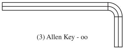
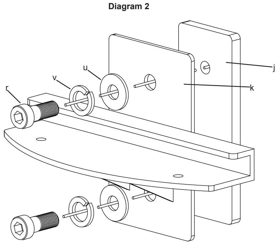
Thread an M8 Allen Bolt (r) through a Spring Washer (v), an M8 Washer (u), the Shelf Bracket (k), and into the Shelf Plate (j). See Diagram 2 for assistance. Loosely tighten the M8 Allen Bolt into the Shelf Plate with an Allen Key (oo). Leave approximately a 1/8 gap between the Shelf Bracket and the Shelf Plate for Step 4. Repeat process for 2nd Shelf Bracket.
Step 3: Wall Bracket Assembly
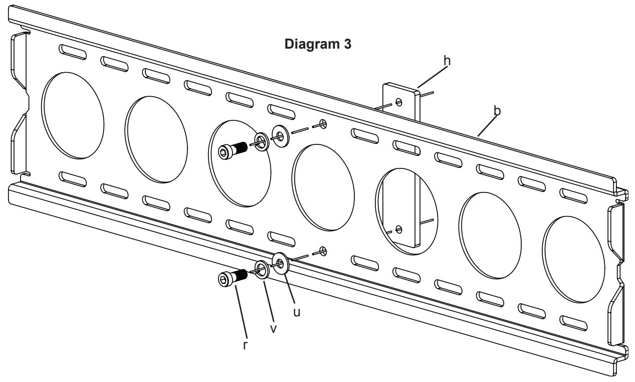
Thread an M8 Allen Bolt (r) through a Spring Washer (v), an M8 Washer (u), through the middle hole in the Wall Bracket (b), and into the Wall Plate (h) as seen in Diagram 3. Loosely tighten the M8 Allen Bolt into the Wall Plate with an Allen Key (oo). Leave approximately a 1/8 gap between the Wall Bracket and the Wall Plate for Step 5.
Step 4: Add Shelf Bracket to Pillar
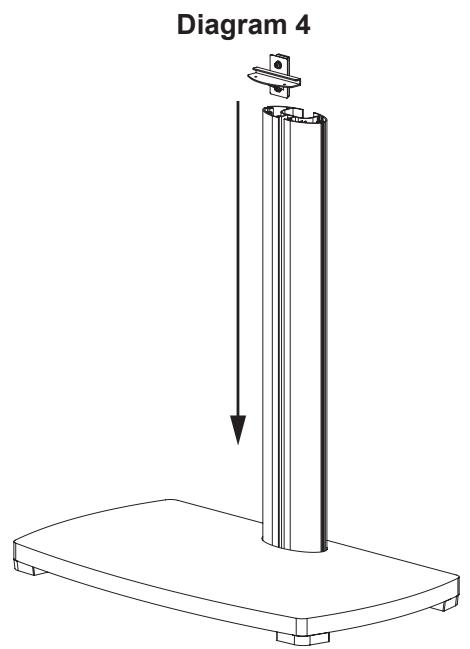
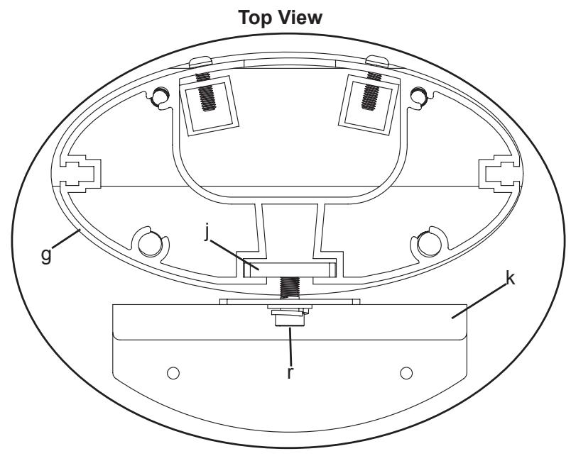
Add the Shelf Bracket Assembly to the Pillar (g) by sliding it down from the top to the desired position on the Pillar. Make sure the Shelf Plate (j) fits into the channel in the Pillar. See the Top View of Diagram 4 for assistance. Once you have the Shelf Bracket Assembly in place, proceed to tighten the M8 Allen Bolts (r) with an Allen Key (oo) so the Shelf Bracket Assembly is firmly in place. Repeat the process for the second Shelf Bracket.
Note: Make Sure The M8 Allen Bolts Are Tight!
Step 5: Add Wall Bracket
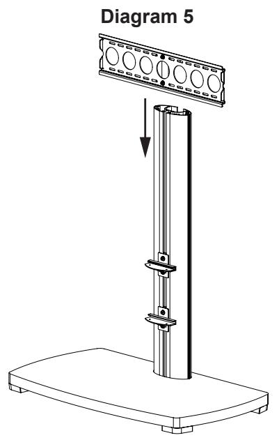
Slide the Wall Bracket Assembly down into place on the Pillar (g). Make sure the Wall Plate (h) fits into the channel in the Pillar as seen in the Top View of Diagram 5. Once the Wall Bracket Assembly is in the desired position, tighten the M8 Allen Bolts (r) with an Allen Key (oo) so the Wall Bracket Assembly is attached to the Pillar. Attach the Wall Bracket Spacers (i) to the Wall Bracket (b) by sliding the Wall Bracket Spacers from the side so the plastic tabs into the correct oval holes on the Wall Bracket. See the Top View of Diagram 5. You may have to loosen the M8 Bolts in the Wall Bracket to have enough space to fit the Wall Bracket Spacers in between the Wall Bracket and the Pillar.
Note: Make Sure The M8 Allen Bolts Are Tight!

Step 6: Add the Glass Shelves
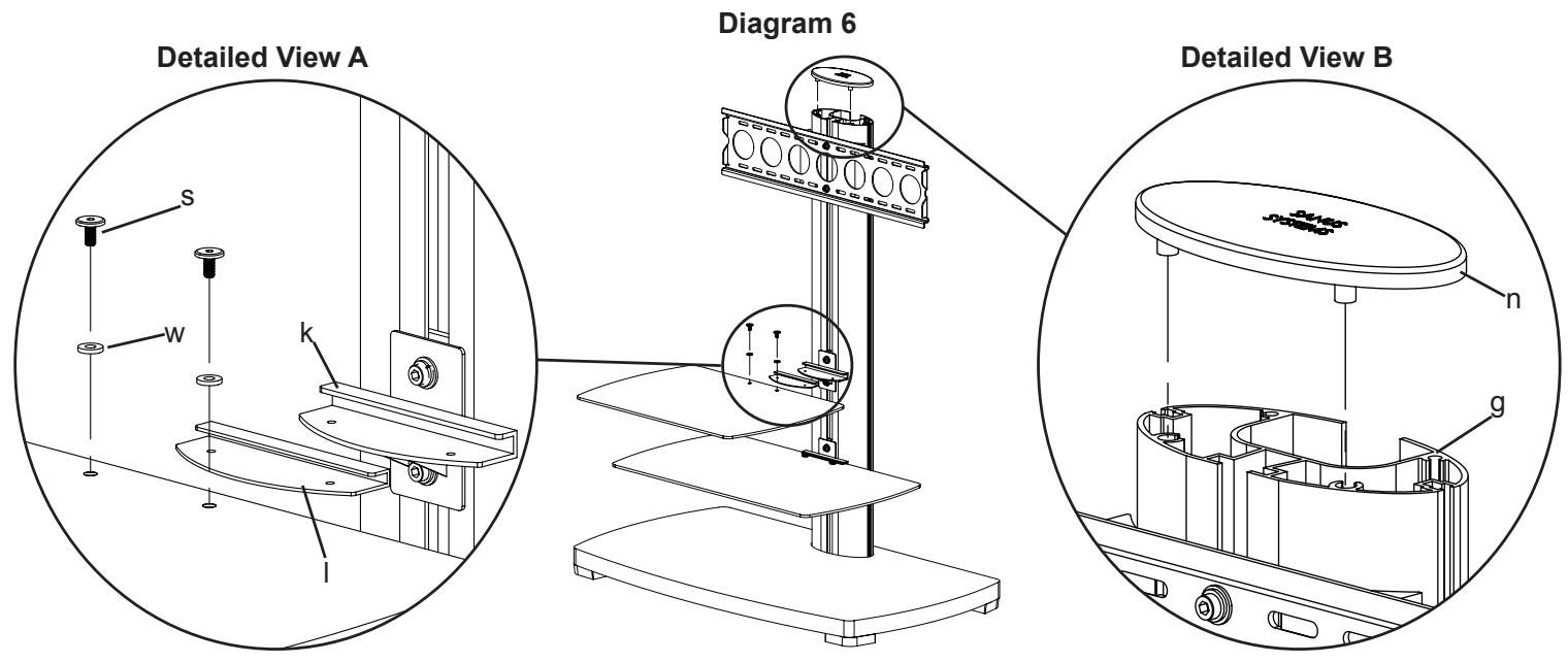
Take the Glass Shelf Washer (l) and insert it onto the Glass Shelf (c,d). Make sure the holes in the Glass Shelf Washer and the Glass Shelf are aligned. Slide the Glass Shelf assembly into the Shelf Bracket (k). Thread each 1/4-20 Allen Bolt (s) down through a Plastic Washer (w), the Glass Shelf and into the Shelf Bracket assembly. Tighten the 1/4-20 Allen Bolts firmly so the Glass Shelf is secured to the Shelf Bracket. See Detailed View A of Diagram 6 for assistance. Repeat the process for the other Glass Shelf.
Next, add the Top Cap (n) to the top of the Pillar (g) by lining up the two plastic dowels on the bottom of the Top Cap with the corresponding pattern on the top of the Pillar as seen in Detailed View B of Diagram 6. Press down firmly on the Top Cap to make sure it is in place.
Note: The smaller Glass Shelf is typically installed above the larger Glass Shelf.
Step 7: Mounting Monitor Brackets to a television with a flat back
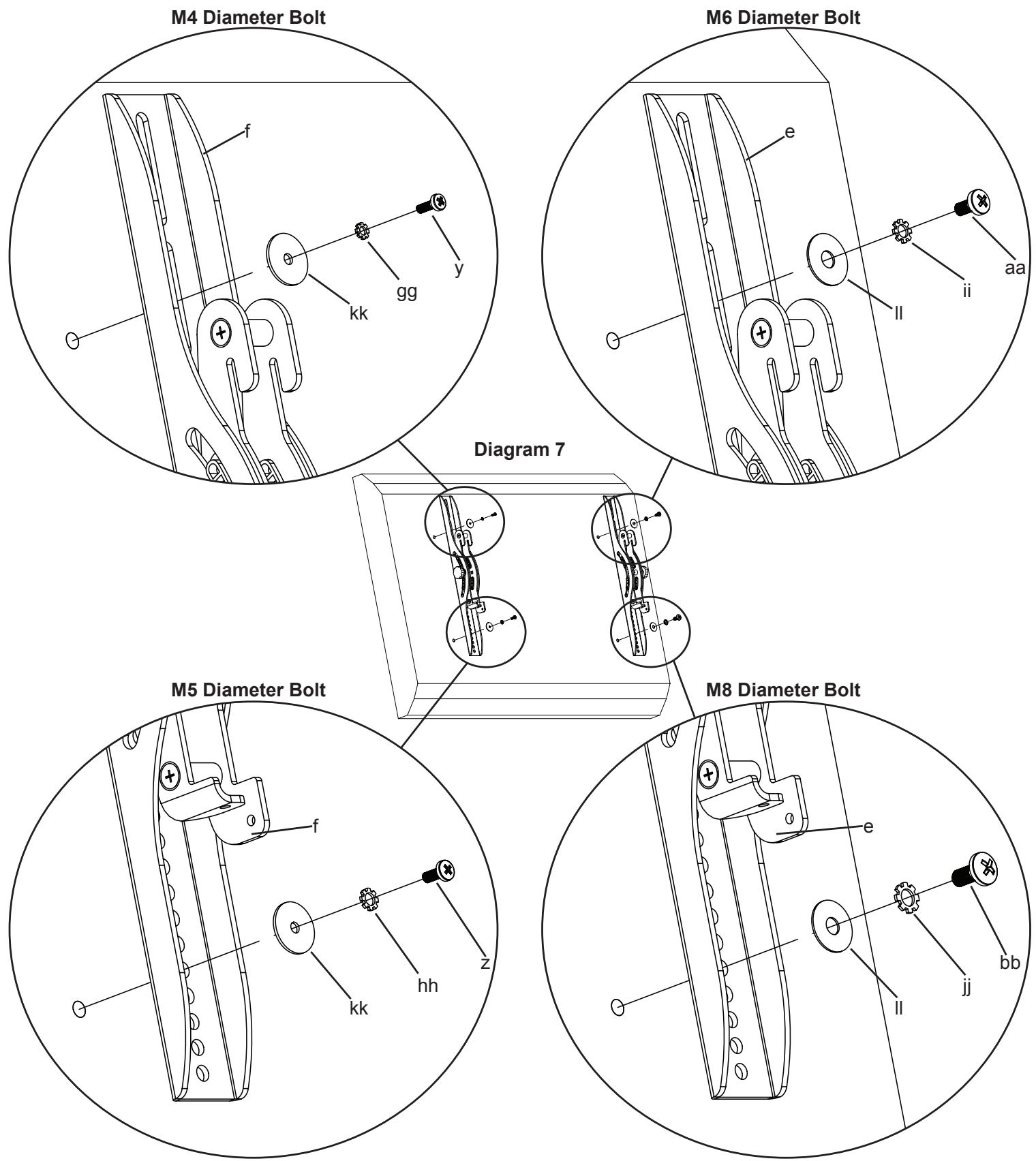
First, determine the diameter of the Bolt (y,z,aa,bb) your TV requires by hand threading them into the threaded insert on the back of the TV. If you encounter any resistance stop immediately! Once you have determined the correct diameter, see the appropriate Diagram below. You will thread the Bolt through the appropriate Lock Washer (gg,hh,ii,jj), a Washer (kk,ll), the Monitor Bracket (e,f), and finally into the TV. Make sure the Monitor Brackets are vertically centered and level with each other. See the appropriate Diagram below.
Note: For televisions with a curved back, or an obstruction near the threaded insert see Step 8.
Step 8: Mounting Monitor Brackets to a television with a curved back or an obstruction near the threaded insert
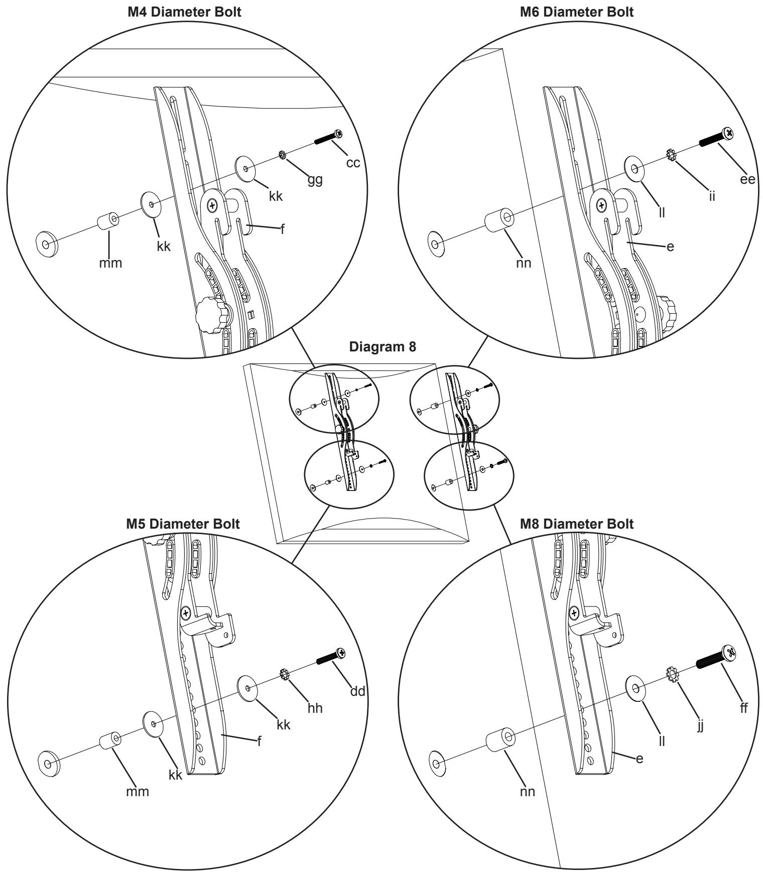
First, determine the diameter of the Bolt (cc,dd,ee,ff) your TV requires by hand threading them into the threaded insert on the back of the TV. If you encounter any resistance stop immediately! Once you have determined the correct diameter, see the appropriate Diagram below. You will thread the Bolt through the appropriate Lock Washer (gg,hh,ii,jj), a Washer (kk,ll), the Monitor Bracket (e,f), a Spacer (mm,nn) and finally into the TV. Make sure the Monitor Brackets are vertically centered and level with each other. See the appropriate Diagram below.

Step 9: Hang TV and Safety Bolt
Warning: Lifting the television may require two people!
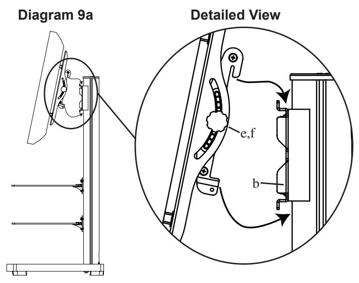
To hang the TV onto the Wall Bracket (b) first hook the Monitor Brackets (e,f) over the top of the Wall Bracket, then let the bottom of the Monitor Brackets rotate in under the bottom of the Wall Bracket as shown in the Detailed View of Diagram 9a.
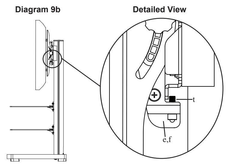
Insert the Safety Bolts (t) into the threaded holes in the bottom of the Monitor Brackets (e,f) and tighten them with the Allen Key (oo) so that they sit behind the bottom tab on the Wall Bracket (b) as shown in the Detailed View of Diagram 9b. Finally set the tension of the knobs on the Monitor Brackets and you are free to adjust your new flat panel TV.
Step 10: Shelf Bracket Cap
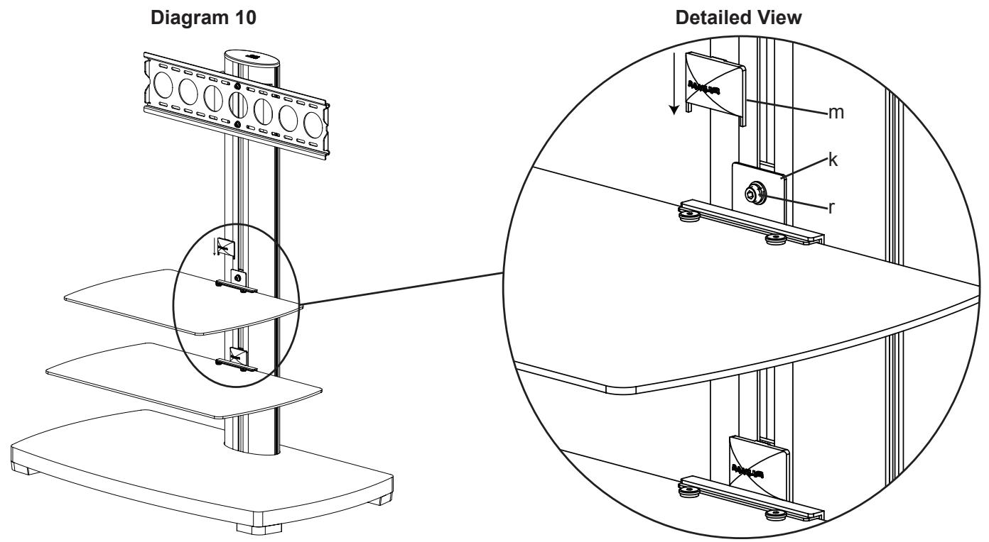
Place the Shelf Bracket Cap (m) over the Shelf Bracket (k) so it hides the M8 Allen Bolt (r) as shown in Diagram 10.
SANUS SYSTEMS
(1) Plaque murale - h*
(2) Entretoise de support de fixation - i*